5.2.5.2 Mechanical Design
This section presents the structural and dynamic analysis of the Coaxial Differential 2-DOF joint, covering Drivetrain Logic (gear reduction, kinematics, and helical profile rationale) and Material Science and Structural Hardening (the transition from FDM polymers to a hybrid steel-Delrin interface).
Final Joint Design — Coaxial Differential with Side-Mounted Motors
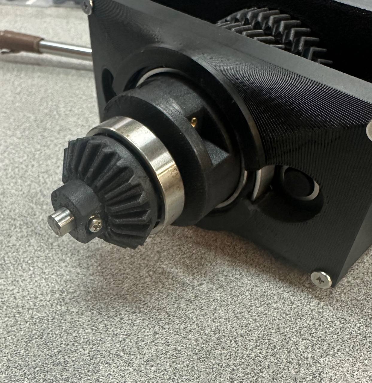
The selection of the Damiao DM-J4310-2EC motors informed the final mechanical architecture: two motors mounted side-by-side horizontally at the base of the arm, each driving a pinion gear that meshes with a central coaxial gear stack. This drivetrain arrangement provides the 3:1 gear reduction while keeping both motors at the pivot point for mass centralisation. Motor 1's gear path connects through a bevel gear to drive the pitch axis (inner shaft), while Motor 2's gear path drives the roll axis (outer housing). Both motors are positioned proximally to achieve the mass centralisation strategy detailed in Design & Ideation.
Click and drag to rotate; scroll to zoom; right-click to pan. Toggle annotations to view key components.
Drivetrain Logic
The gear reduction and kinematic derivation are presented as a unified system because the differential coupling between the two axes means that gear properties directly affect the kinematic equations, and vice versa.
3:1 Helical-Spur Gear Reduction
Each motor drives the central gear stack through a 3:1 reduction: the motor must rotate 3 full revolutions (1080° / 18.84 rad) to produce 1 full revolution (360° / 6.28 rad) at the output. This reduction delivers 3× the motor's native torque at the joint, while reducing the output speed to one-third of the motor's shaft speed.
Helical Gear Profile — Overlap Ratio & Torsional Rigidity
The selection of a helical gear profile (as opposed to straight-cut spur gears) was not solely motivated by backlash reduction. The angled tooth profile provides a significantly higher contact ratio (overlap ratio), defined as the average number of teeth simultaneously in mesh. For the selected helical geometry, this ratio exceeds 1.5, meaning that at any given instant, at least one-and-a-half tooth pairs share the transmitted load.
This property is critical for the boxing application. During a snap-back command (proportional retraction from the strike apex), the motors undergo rapid direction reversal, generating an impulse torque that propagates through the gear train. With straight-cut spur gears (overlap ratio ≈ 1.0), this impulse would be borne by a single tooth pair, concentrating stress and accelerating fatigue in 3D-printed PLA teeth. The helical profile distributes this impulse across multiple tooth pairs, increasing the drivetrain's torsional rigidity and extending the fatigue life of the 3D-printed gears under repeated high-velocity sparring cycles.
Closed-Form Kinematic Equations
The following equations define the relationship between the raw motor encoder space (mr = roll motor, mp = pitch motor) and the joint output space (θpitch, θroll). The model uses three calibrated sign parameters: sr (roll motor sign, ±1), sp (pitch motor sign, ±1), and c (bevel gear coupling direction, ±1). These parameters are determined by the 4-test calibration probe and account for mirror symmetry between left and right arms as well as bevel gear mounting orientation.
Show full equations
Motor → Joint (Forward Conversion)
θroll = sr ·
(mr − or) / G
(Eq. 1)
θpitch = sp ·
[(mp − op) + c ·
(mr − or)] / G
(Eq. 2)
where G = 3 (helical-spur gear reduction) and or, op are the calibrated home offsets.
Eq. 2 reveals the differential coupling: pitch depends on the sum of the pitch motor displacement and a coupling-weighted roll motor displacement. When both motors rotate in the same direction, the coupling term cancels the bevel walking; this is the pure roll condition.
Joint → Motor (Inverse Conversion)
Δr = (θroll / sr)
· G,
mr = Δr + or
(Eq. 3)
mp = [(θpitch / sp)
· G − c · Δr]
+ op
(Eq. 4)
Eq. 4 is the firmware's primary command equation. The subtraction of c · Δr is the software decoupling term that cancels the parasitic walking effect in real-time.
Forward Kinematics (Rotation-Around-Arm-Axis Model)
At θpitch = 0, the arm points straight outward (perpendicular to the body). The arm body rotates around this tube axis, so the pitch swing plane rotates with the body. This produces:
dx = sx · cos(θpitch)
dy = sin(θpitch) · cos(θroll)
dz = sin(θpitch) · sin(θroll)
where sx = −1 (left arm) or +1 (right arm). The Z-component sin(θpitch)·sin(θroll) correctly models the physical observation that both CW and CCW body rotation with bevel walking cause the arm to tilt upward.
Calibration Probe & Validated Results
A dedicated motor diagnostic script, motor_probe.py,
systematically determines all three sign parameters for each arm.
The operator stands in front of the robot for
all tests on both arms:
| Test | Motor Command | Observation | Determines |
|---|---|---|---|
| 1 | +pitch motor only | Arm swings FORWARD or BACKWARD? | sp |
| 2 | +roll motor only | Top tilts TOWARD ME or AWAY? | sr |
| 3 | +roll motor only (repeat) | Bevel walks FORWARD or BACKWARD? | c |
| 4 | Both motors same direction | Verify: pure roll, no pitch? | Confirmation |
Left arm: sp = −1, sr = +1, c = −1
Right arm: sp = +1, sr = −1, c = −1
Both arms share c = −1 (same bevel arrangement). Signs are mirrored between arms (symmetric geometry).
The Differential Walking Effect
When the roll motor rotates while the pitch motor is held stationary, the bevel gear inside the housing "walks" around the driving gear. This produces an automatic pitch change proportional to the housing's angular displacement, characterised by the coupling parameter c.
To achieve pure roll, the firmware commands both motors to move in the same direction at identical speeds. The coupling term in Eq. 4 enforces this automatically. Conversely, this walking effect is intentionally exploited during jab windups, where opposite-direction motor commands produce a "rearing" motion that lifts the arm before the downward strike (see System Troubleshooting Appendix — Tactical Walking).
The enforcement of safe pitch limits requires joint-space clamping rather than static independent motor bounds, owing to the differential coupling. The firmware implementation is documented in System Troubleshooting Appendix — Joint-Space Pitch Clamping.
Material Science & Structural Hardening
The CDE Fair structural failures and the subsequent engineering response are documented as a material science transition, from a pure FDM polymer assembly to a hybrid interface combining metallic and polymer components, each selected for its specific mechanical properties.
CDE Fair Structural Failures: Root-Cause Analysis
During the CDE Fair demonstration, two critical failure modes were observed:
| Failure | Location | Root Cause | Stress Mode |
|---|---|---|---|
| Shaft fracture | Motor-to-gear and gear-to-bevel interfaces | PLA shafts failed under dynamic torsional loading during direction reversals | Shear stress at the D-flat interface — PLA exhibits acceptable tensile strength but poor shear resistance along FDM layer lines |
| Arm proximity impact | Arm housing structure | Arms mounted too close to the sparring partner, causing unintended impacts to the arm body rather than padded targets | Impact bending loads on non-reinforced housing walls |
The Hybrid Interface Solution
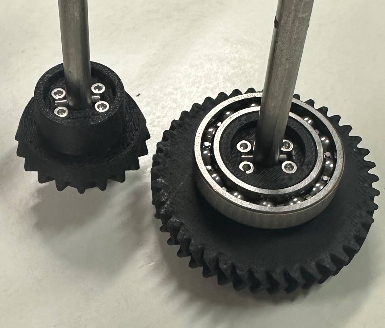
The post-CDE-Fair revision replaced the monolithic PLA drivetrain interface with a three-material hybrid assembly, assigning each material to the stress mode it is best suited to resist:
Material Selection Rationale
| Component | Material | Primary Stress Mode | Property Exploited |
|---|---|---|---|
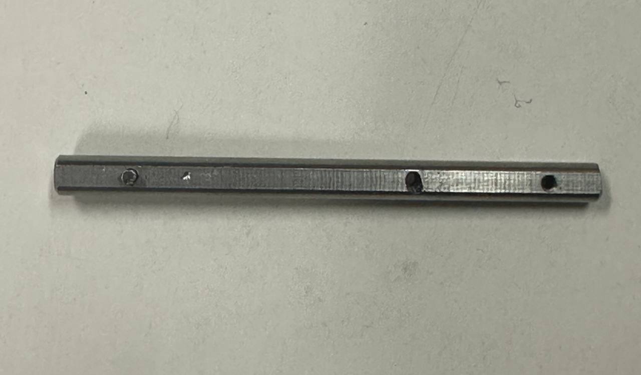
| Central shaft (6 mm) | Stainless Steel | Torsion / Shear | The D-flat profile provides a positive mechanical interlock between the shaft and the gear bore, eliminating the relative rotation that caused FDM layer-line delamination. Stainless steel's inherent torsional rigidity ensures zero angular compliance at the shaft-gear interface, directly addressing the shear failure mode observed in the original PLA shaft |
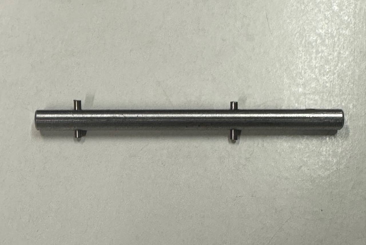
| Alignment pin (2 mm) | Delrin (POM) | Vibration / Impact | Absorbs impulse vibration at the gear interface rather than transmitting it into the housing |
| Reinforcement screws (M2) | Steel | Tension / Retention | Clamp the Delrin pin and 3D-printed gear together; serve as the primary force-translation interface between the pin and the printed components |
| Housing & gears | PETG (FDM) | Compression / Structure | Acceptable compressive strength for housing walls; rapid prototyping iteration capability; load-bearing walls thickened post-CDE-Fair |
The key engineering insight was that the PLA shafts did not fail in tension (PLA's strongest mode); they failed in shear at the D-flat motor interface, where torsional loads caused delamination along the FDM layer lines. The solution was not simply "replace plastic with metal," but to assign each material to the stress mode it resists best: stainless steel for torsional rigidity, Delrin for vibration damping, and PLA retained only for structural housing where compressive loads dominate.
FDM Filament Selection for Gear Components
The mechanical integrity of the coaxial differential joint is fundamentally bounded by the material properties of its 3D-printed gears and housing. The following table evaluates candidate FDM filaments against the four properties most critical to gear performance in this application: stiffness (resistance to tooth deflection), impact toughness (survival of reversal shocks), wear resistance, and thermal stability.
| Material | Stiffness (Modulus) | Impact | Wear | Heat Deflection | Print Difficulty |
|---|---|---|---|---|---|
| PLA | Very High (~3.5 GPa) | Low (brittle) | Low | ~55°C | Very Easy |
| PLA-CF | Extremely High | Very Low (brittle) | Moderate | ~55°C | Easy (hardened nozzle required) |
| PETG | Moderate (~2.0 GPa) | High (ductile) | Low | ~75°C | Moderate |
| PETG-CF | High (~2.0 GPa) | Moderate | Moderate | ~80°C | Moderate (hardened nozzle required) |
| PA6 Nylon | Moderate–High | Very High | Very High (self-lubricating) | ~85°C | Difficult (hygroscopic, warping) |
Note on Carbon-Fibre FDM Filaments (PLA-CF, PETG-CF)
Carbon-fibre variants of FDM filaments are marketed as high-stiffness alternatives to their base polymers. However, the reinforcement mechanism in FDM filament is fundamentally different from that in continuous-fibre or woven composites:
Show full technical analysis
FDM-grade CF filament contains short chopped fibres (typically <200 µm), randomly oriented within the polymer matrix. These fibres do not form a continuous load-bearing network, and the resulting in-plane stiffness gains are marginal (approximately 10 to 20 percent relative to the base polymer), compared to the orders-of-magnitude improvement observed in woven or continuous-fibre composites.
Furthermore, the rigid fibre ends act as crack initiation sites under dynamic loading. Fibre inclusions also prevent adequate polymer chain fusion between successive printed layers, thereby reducing inter-layer bond strength and rendering the part significantly more brittle across the Z-axis than its non-CF counterpart.
The net effect for gear applications is that CF variants offer marginally higher in-plane stiffness (beneficial for tooth profile accuracy) but substantially reduced impact toughness and inter-layer strength. For gear teeth subjected to repeated reversal shocks, this trade-off is unfavourable. Plain PLA offers higher stiffness than PETG-CF at the component level (3.5 GPa versus approximately 2.0 GPa) and prints with significantly better layer adhesion, making it the preferred choice for gear teeth.
Selected Material Strategy: PETG Gears & Housing
| Component | Material | Rationale |
|---|---|---|
| Gear teeth & housing | PETG | Ductility for impact absorption; ~20°C higher thermal ceiling than PLA for sustained operation |
Supplementary Structural Revisions
Two supplementary structural modifications were implemented in the post-CDE-Fair revision. First, the number of intermediate 3D-printed couplings in the torque path between the motor and the gear stack was reduced, thereby minimising the number of potential shear-failure interfaces and improving rotational alignment. Second, the cross-sections of the housing walls and gear mount flanges were increased to raise the second moment of area, improving resistance to bending loads from off-axis impacts.