5.2.4 Mechanical Design for Padding
Foam Construction
The striking surface uses polyethylene foam wrapped in water-resistant faux leather. The design draws from commercial boxing focus mitts, which use multi-layer EVA and PU foam stacks to balance responsiveness with cushioning. For BoxBunny, a simpler single-material foam was sufficient because the spring return mechanism (described below) handles the rebound rather than the foam itself. Each pad weighs approximately 150 g. The faux leather outer layer protects the foam from sweat and surface wear during extended training sessions.
Strike-Zone Placement
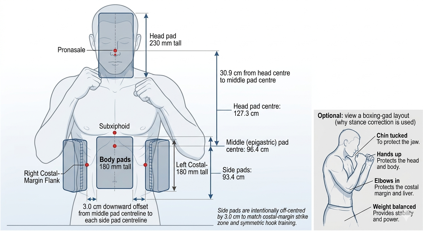
The final mount geometry was designed using pronasale (nose tip), subxiphoid (epigastric region), and right and left costal-margin flank targets in boxing guard stance (Drillis and Contini, 1966; Gordon et al., 2014).
Target Population and Guard Model
The design target covers users from 150 to 190 cm. Final pad centres are set from the mean of four profile calculations (150F, 150M, 190F, 190M) after applying boxing-guard posture correction. This keeps the fixed frame practical for the whole range while preserving realistic body-zone order in stance.
Revised Ergonomic Outputs Used for CAD
The final robot uses the revised mean guard values: head pad centre at 127.3 cm, epigastric pad centre at 96.4 cm, and both side pads at 93.4 cm. This gives a head-to-epigastric gap of 30.9 cm and a fixed epigastric-to-side-pad offset of 3.0 cm downward (Drillis and Contini, 1966; Gordon et al., 2014).
| Design metric (boxing guard) | Value | Applied in mechanical layout |
|---|---|---|
| Head pad centre (pronasale) | 127.3 cm | Top target plane |
| Middle pad centre (epigastric) | 96.4 cm | Reference centreline for torso pads |
| Side pad centre (liver, right) | 93.4 cm | 3.0 cm below middle pad centreline |
| Side pad centre (stomach-side, left) | 93.4 cm | Mirrored to right-side height |
| Head to middle pad gap | 30.9 cm | Primary vertical spacing chain |
| Middle to side pad off-centre | 3.0 cm down | Final selected torso offset rule |
Pad Size and Coverage with 3.0 cm Off-Centre
The final body pad face remains 180 mm by 130 mm. With a 3.0 cm centre offset, the side pads are clearly lower than the middle pad but still overlap in usable strike area during motion. This avoids a dead vertical strip while preserving the intended hook target level.
| Iterations | Body pad face (H x W) | Sizing basis |
|---|---|---|
| 1 to 3 | ~150 mm x 100 mm | Boxing glove face approximation |
| 4 to 5 (final) | 180 mm x 130 mm | Population coverage, edge contact, and strike precision |
Head Pad Sizing and Separation
The head pad remains 200 mm by 230 mm. The revised chain gives a 30.9 cm centre-to-centre gap from head pad to middle body pad in boxing guard, which matches the practical verification range (Pheasant and Haslegrave, 2006).
Why Side Pads Are Off-Centred by 3.0 cm
The side targets are anchored to the costal-margin flank zone used in the revised ergonomics analysis. In this model, the flank strike band is 3.0 cm below the subxiphoid reference. Therefore, both side pads are mounted 3.0 cm below the middle pad centreline by design, not by tuning.
The left side uses the same height as the right side for symmetric hook training and repeatable mounting geometry. In oral terms, the rule is simple: set the middle pad first, then drop each side pad exactly 3.0 cm.
| Profile | Epigastric Centre (stance) | Liver and stomach-side Centre (stance) | Gap (epigastric minus lower body pad) |
|---|---|---|---|
| 150F | 83.5 cm | 80.5 cm | 3.0 cm |
| 150M | 84.7 cm | 81.7 cm | 3.0 cm |
| 190F | 107.9 cm | 104.9 cm | 3.0 cm |
| 190M | 109.4 cm | 106.4 cm | 3.0 cm |
| Mean | 96.4 cm | 93.4 cm | 3.0 cm |
With 180 mm body pads (9.0 cm half-height), the 3.0 cm off-centre creates a controlled vertical overlap between middle and side targets. That gives a continuous strike corridor for combinations while still making the side pads read as a lower hook band.
Pad Edge Contact and Spring Mechanism Clearance
The 130 mm pad width was chosen so that in the natural extended position the upper edge of each liver or stomach-side pad just meets the lower edge of the epigastric pad. There is no gap between adjacent pads at rest. When a pad is struck, the spring mechanism compresses it backward. As it moves back, the contacting edges separate and the pad retracts freely without the face of one pad bearing against the face of an adjacent pad. All three body pads are independently spring-loaded, so each retracts and returns independently. The edge contact at rest is a design choice to avoid visible gaps in the strike surface while still allowing each pad to travel its full spring stroke without interference.
Final Pad Centre Heights
| Pad | Centre Height from Ground | Basis |
|---|---|---|
| Epigastric region | 96.4 cm | Mean stance-corrected subxiphoid reference |
| Liver (right side) | 93.4 cm | Fixed 3.0 cm below epigastric centreline |
| Stomach-side (left side) | 93.4 cm | Mirrored to liver height for symmetric hook training |
| Epigastric to lower body pad gap | 3.0 cm centre-to-centre | Constant geometry from revised ergonomic model |
| Head pad bottom to epigastric pad top | ~10.4 cm edge-to-edge | From centres 127.3 cm and 96.4 cm with 230 mm and 180 mm pad heights |
Mount Design Evolution
The padding mount went through five iterations, all 3D-printed in PLA and attached to the robot's 80x80 mm aluminium V-slot extrusion frame.
Iteration 1: Direct Foam-to-Frame Mount
A single PLA bracket design was used for both the front and side striking zones. The mount fractured after one strong punch at its thinnest cross-section. Using identical geometry for all three positions also produced unnatural punching angles, as the flat bracket did not account for the angular difference between a straight jab and a side hook.
Iteration 2: Thicker Mount, Dedicated Front and Side Designs
The mount cross-section was made substantially thicker. A dedicated front mount and an angled side mount (mirrorable for left/right) were created. This design survived the "Robotics Meets AI Showcase" in late January 2025, including full-power strikes from two professional boxers and a boxing promoter. However, the rigid attachment transmitted the full impulse into the aluminium frame, causing the entire robot to shake visibly after strong punches.
Iteration 3: Spring Return Mechanism (First Attempt)
A compression spring was introduced between the frame-side mount and a separate foam-side mount. The assembly chain is: aluminium frame, frame-side mount (holds one end of the spring), spring, foam mount (holds the other end of the spring and the IMU sensor), foam. The frame-side mount has dedicated front and side versions, while the foam mount is a shared design used for both. Pyramid-shaped reinforcement walls were added to the frame-side housing. The IMU was positioned near the corner of the foam mount in this iteration.
Three problems were discovered:
- Friction-fit failure: Spring OD varied between units, making some frame-side mounts too loose and others too tight.
- Spring too stiff: Specified for an assumed 1 kg mass, but the foam is only 150 g (see calculations below).
- Side angle still off: Side pads were positioned too far out, making hooks feel unnatural.
Iteration 4: Spring-Loaded Box (Pre-Final Baseline)
Inspired by spring-loaded box mechanisms, the spring now sits inside a box-shaped housing that constrains lateral movement. The exact spring OD no longer matters for fit, eliminating the friction-fit problem. The spring was re-specified for the actual 150 g foam mass. The free length was shortened from 180 mm to 140 mm to keep the foam closer to the body during rotation. The aluminium-frame mount is split into two halves and printed sideways, orienting layer lines perpendicular to side impacts for delamination resistance. The side padding angle was corrected. The IMU sensor was relocated from the corner (iteration 3) to the bottom edge, centered horizontally, for more consistent impact readings.
Iteration 5: Anatomy-Guided Anti-Rotation Mount (Final Design)
The new final iteration keeps the spring-loaded box architecture from Iteration 4 and applies the validated Strike-Zone Placement targets directly to mount placement. The torso mounts were re-positioned so both side pads are deliberately off-centred by 3.0 cm below the middle epigastric centreline. Head-to-middle spacing is set to 30.9 cm centre-to-centre. This ties the CAD directly to the revised ergonomic model and makes the side hook band lower by construction, not by trial and error.
To solve pad rotation after repeated impacts, anti-rotation guides were added to the moving pad carrier. The guides constrain twisting about the mounting axis while preserving intended spring compression along the punch direction. This improved impact repeatability and keeps IMU orientation stable over long training sessions.
The strike-zone placement constraints above are reflected primarily in the final Iteration 5 mount geometry; the spring discussion below focuses on impact-response tuning.
Spring Calculations
Spring selection evolved in two stages driven by different design priorities. Iteration 3 used a sag-control requirement as the primary constraint. Iterations 4 and 5 shifted priority to impact absorption and IMU signal quality after the enclosed box guide removed sag as a practical risk and the actual pad mass was measured.
Stage 1: Sag-Driven Requirement (Iteration 3)
Before the box housing was introduced, the mount was treated as a partially unsupported horizontal spring system. The conservative design assumption was an end-effector mass of 1.0 kg. Static load is:
Fstatic = m × g = 1.0 × 9.81 = 9.81 N
For candidate spring rates, static axial sag follows Hooke's law:
xsag = F / k
Using the 1 kg load case, the design-space checks are:
k = 33 N/mm → xsag = 9.81 / 33 = 0.30 mm
k = 20 N/mm → xsag = 9.81 / 20 = 0.49 mm
k = 10 N/mm → xsag = 9.81 / 10 = 0.98 mm
This is why the early spring shortlist sat in the 25 to 30 N/mm range: it kept static sag below 0.40 mm for the assumed load. At this stage the design goal was purely sag prevention. Impact isolation was not yet a governing requirement because no enclosed guide existed to separate the foam mount from the frame.
Stage 2: Measured Mass and Impact-Isolation Requirement (Iterations 4 to 5)
Prototype weighing showed the moving padding assembly was approximately 150 to 200 g, not 1 kg. Using a midpoint of 0.175 kg:
Fstatic = 0.175 × 9.81 = 1.72 N
xsag = 1.72 / 8 = 0.21 mm
Sag at the actual mass is negligible regardless of spring rate in the practical range, and the boxed guide in Iteration 4 constrains lateral droop mechanically. Spring selection therefore shifted to a new governing requirement: the spring must compress far enough under a representative punch load to absorb the impact in the foam mount rather than transmitting a rigid impulse to the aluminium frame.
For the spring to absorb the impact rather than transmit it to the frame, the foam mount must travel a meaningful distance on every representative strike. A minimum compression of 20 mm ensures the impulse is spread over a measurable displacement rather than passing through as a near-rigid contact. An upper bound of 60 mm keeps the stroke within the enclosure geometry without risk of coil bind at the 140 mm free length. This 20 to 60 mm working stroke became the governing isolation criterion for spring rate selection in Iterations 4 and 5.
The design load range was established from literature. Pierce et al. (2006) measured peak punch forces of 1,670 to 4,096 N across professional boxing matches. Walilko et al. (2005) reported a mean peak of approximately 3,427 N for Olympic-level competitors. BoxBunny targets recreational to intermediate users, not professional athletes. Consistent with the lower end of the Pierce et al. range for lighter or less-trained fighters, a working design envelope of 200 to 500 N was adopted.
At 8 N/mm, this load range produces compressions of 25 to 63 mm, which falls within the 20 to 60 mm isolation window throughout. The rejected Iteration 3 spring rate of 25 to 30 N/mm produces only 6.7 to 20 mm at the same load range, missing the lower bound entirely at lighter strikes and only reaching the threshold at the upper limit of 500 N. This is why the stiffer spring was unsuitable once impact isolation replaced sag prevention as the governing requirement.
For the selected spring rate of 8 N/mm, compression under this load range is:
F = 200 N → x = 200 / 8 = 25.0 mm
F = 300 N → x = 300 / 8 = 37.5 mm
F = 400 N → x = 400 / 8 = 50.0 mm
F = 500 N → x = 500 / 8 = 62.5 mm
These values place the compression stroke in the 25 to 63 mm range (2.5 to 6.3 cm) across the full recreational load envelope. The foam mount travels visibly on every representative strike, confirming that the spring absorbs the impulse rather than the frame. Relative to the 140 mm free length, the 500 N design check gives 62.5 mm compression, which is 45% of free length, well within the controllable stroke of the current enclosure geometry.
| Applied load | Predicted compression | Interpretation |
|---|---|---|
| 200 N | 25.0 mm | Responsive for average recreational strikes |
| 300 N | 37.5 mm | Clear cushioning under stronger punches |
| 400 N | 50.0 mm | High absorption while remaining controllable |
| 500 N design check | 62.5 mm | Selected safe upper working case for current layout |
Stage 3: Spring-Mass Decoupling and IMU Signal Quality
A secondary but important consequence of the spring selection is its effect on IMU measurement accuracy. The IMU sensor is mounted on the foam mount, the moving side of the spring assembly. When a punch lands, the spring mechanically decouples the foam mount from the rigid aluminium frame. The IMU therefore sees only the local acceleration of the foam assembly driven by the fist contact. Without the spring, the foam mount would be rigidly coupled to the frame, and the IMU signal would contain the punch impulse superimposed on structural vibrations from the chassis, motor commutation noise, and gear-mesh frequencies travelling through the aluminium extrusion.
The spring-mass system has a natural frequency that determines its filtering behaviour. Using the measured pad assembly mass of 0.150 kg and the selected spring rate of 8 N/mm:
fn = (1 / 2π) × √(k / m) = (1 / 2π) × √(8000 / 0.150) ≈ 36.7 Hz
Vibration energy from the robot drive system (motor commutation, bearing noise) occurs predominantly above this frequency. The spring-mass assembly attenuates these high-frequency inputs before they reach the IMU, leaving a clean signal dominated by the punch impulse itself. A typical punch force peak has a rise time of 10 to 50 ms (Cheraghi et al., 2014), corresponding to spectral content well below the 36.7 Hz natural frequency, so the punch signal passes through the assembly without attenuation.
This filtering effect directly supports the CV and IMU sensor fusion pipeline. The fusion node uses a 5.0 m/s² acceleration threshold on the IMU to trigger a punch detection event. A rigidly mounted IMU exposed to chassis vibration would produce elevated baseline noise, making this threshold unreliable. The spring isolation keeps the foam-mount IMU signal clean enough for the threshold to discriminate genuine impacts from background noise consistently across training sessions.
| Parameter | Iteration 3 (rejected) | Iteration 4 baseline (retained in Iteration 5 final) |
|---|---|---|
| Free length | 180 mm | 140 mm |
| Outer diameter | 35 to 40 mm | 35 mm |
| Wire diameter | 5.5 to 6.5 mm | 4 mm |
| Spring rate | 25 to 35 N/mm | 8 N/mm |
| Material | Music wire | Music wire (ASTM A228) |
| Type | Compression, heavy duty | Compression, closed and ground ends |
| Calculated sag (static) | 0.33 mm (at 1 kg) | 0.18 mm (at 150 g) |
| Compression at 500 N | 14.3 to 20.0 mm | 62.5 mm |
| Spring-mass natural frequency | 72 to 96 Hz (at 150 g) | 36.7 Hz (at 150 g) |
Future Softer Spring Direction
Since sag is no longer a governing requirement in Iterations 4 and 5, future revisions can test softer springs mainly for feel tuning. For reference, at 500 N: k = 5 N/mm gives 100 mm compression, while k = 4 N/mm gives 125 mm compression. These can improve forgiveness but need stroke and coil-bind checks in the same box geometry.
Future Work: TPU Filament
A potential future improvement is to replace the separate foam, spring, and PLA mount with a single-piece TPU (thermoplastic polyurethane) print. TPU is a flexible elastomer that could act as the striking surface, the return mechanism, and the structural mount simultaneously.
Horizontal Honeycomb Concept
A promising approach is a horizontally oriented honeycomb lattice printed in TPU. When a honeycomb structure is rotated 90 degrees so the hexagonal tubes run horizontally, it becomes very rigid along the tube axis (resisting lateral sway) but compresses like an accordion when pushed from the striking direction. This produces unidirectional dampening: high absorption in the punch direction with zero lateral compliance. This property is well suited to a padding mount that must absorb frontal impacts without swaying sideways.
Manufacturing Considerations
TPU print speeds must be kept to 15 to 30 mm/s to avoid extrusion inconsistencies, making large parts time-intensive. Manufacturing defects such as stringing, bulging, and buckling become more pronounced with larger unit cell sizes in open-cell topologies, while closed-cell designs such as honeycombs produce significantly fewer defects and superior load resistance (Di Caprio et al., 2025).
Moisture Sensitivity
TPU is hygroscopic, meaning it absorbs moisture from the environment during printing. Extended print durations increase the exposure window, and absorbed moisture causes polymer chains to break down during heating, degrading both surface finish and mechanical strength (Di Caprio et al., 2025). For a part of this size, a dry-box filament feed system would be necessary.
Future Work: Variable Head-Torso Ratio
The current design uses a fixed 30 cm head-torso separation derived from mean anthropometric proportions. In practice, the ratio between head and torso height is not constant across statures: shorter individuals tend to have a proportionally smaller head-torso gap than taller individuals (approximately 26 cm at 150 cm versus 33 cm at 190 cm). A future revision could introduce a second degree of freedom, for example a secondary linear actuator or adjustable mounting rail, to allow the head-torso spacing to scale with user height. This would improve anatomical accuracy at the extremes of the operating range, at the cost of additional mechanical complexity and calibration.
References
- Di Caprio, F., Franchitti, S., Borrelli, R., Ciminello, M., Morano, C. and Greco, A. (2025). Design of Flexible TPU-Based Lattice Structures for 3D Printing: A Comparative Analysis of Open-Cell Versus Closed-Cell Topologies. Polymers, 17(10), 1299.
- Pheasant, S. and Haslegrave, C.M. (2006). Bodyspace: Anthropometry, Ergonomics and the Design of Work, 3rd ed. CRC Press.
- Drillis, R. and Contini, R. (1966). Body Segment Parameters. Technical Report No. 1166-03, School of Engineering and Science, New York University.
- Gordon, C.C. et al. (2014). 2012 Anthropometric Survey of U.S. Army Personnel: Methods and Summary Statistics. Report No. NATICK/TR-15/007.
- Pierce, J.D., Reinbold, K.A., Lyngard, B.C., Goldman, R.J. and Pastore, C.M. (2006). Direct Measurement of Punch Force During Six Professional Boxing Matches. Journal of Quantitative Analysis in Sports, 2(2).
- Walilko, T.J., Viano, D.C. and Bir, C.A. (2005). Biomechanics of the head for Olympic boxer punches to the face. British Journal of Sports Medicine, 39(10), 710-719.